|
 |
Circuits designed by David Johnson, P.E.
Last Updated on:
Monday, December 25, 2017 02:09 PM
List of Dave's Circuit Designs
The contents & graphics
of Discovercircuits.com are copyright protected.
LINKING to Dave's circuits is permitted but DO NOT COPY any files to your WEB
SITE server |
|
|
|
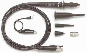
X100 Scope
Probe
Designed by Dave Johnson May, 2010 |
| A 10M load a typical X10
oscilloscope probe will produce large measurement errors and will influence the
circuit operation. To reduce the effect such a probe has on the circuit, I
reach for my X100 scope probe. My probe, with its 100M impedance, is a
commercially made device but if you want to make one, it is not hard to do.
|
|
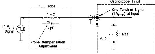
| A typical oscilloscope probe
circuit is shown below. This classic model has a X1 and a X10 position.
In the X1 position, the signal collected at the tip goes straight into the 1M
input of the scope. In the X10 position the signal between the probe tip
and the scope input is attenuated by factor of ten by including a 9M resistor
between the probe tip and the scope input. A trim capacitor in parallel
with the 9M resistor is included and is adjusted to form a clean square wave on
the scope screen, when the probe tip is connected to the 1KHz calibration
signal, which many scopes provide. |
|
|
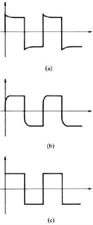
| To change the probe to a X100
device, the 9M resistor has to be changed to 100M. The trim capacitor may
also have to be changed but often the existing cap will work. Adjust the trim capacitor for a
clean square wave signal shown in (c) below" |
|
 |
|
Data sheet for a X100 scope
probe:
http://www.tpi-thevalueleader.com/products/oscilloscopeProbes/TAW Differential Probes-0705.pdf |
| |
|
|
|
|
List of
Dave's
Circuits
List of Circuits from DC Magazine
eMail David A.
Johnson, P.E. about this circuit
|
|
|
|
|
|